Modern Ethernet cables are made up of 8 wires terminated with 8P8C connectors. The wires are twisted together in pairs to reduce crosstalk and to make it easier for transceivers on either end to reject common mode noise. Longer and higher speed cables may also use shielding to protect the entire cable and/or each individual twisted pair
Today I’m building an cable using Category 6a S/FTP cable which includes both a grounded, woven wire mesh to shield the whole cable (S: Shielded) and foil shields for each pair inside (FTP: Foil-shielded Twisted Pair). Like most wires Cat6 is available on large spools and each finished cable starts by cutting off a piece long enough for the cable
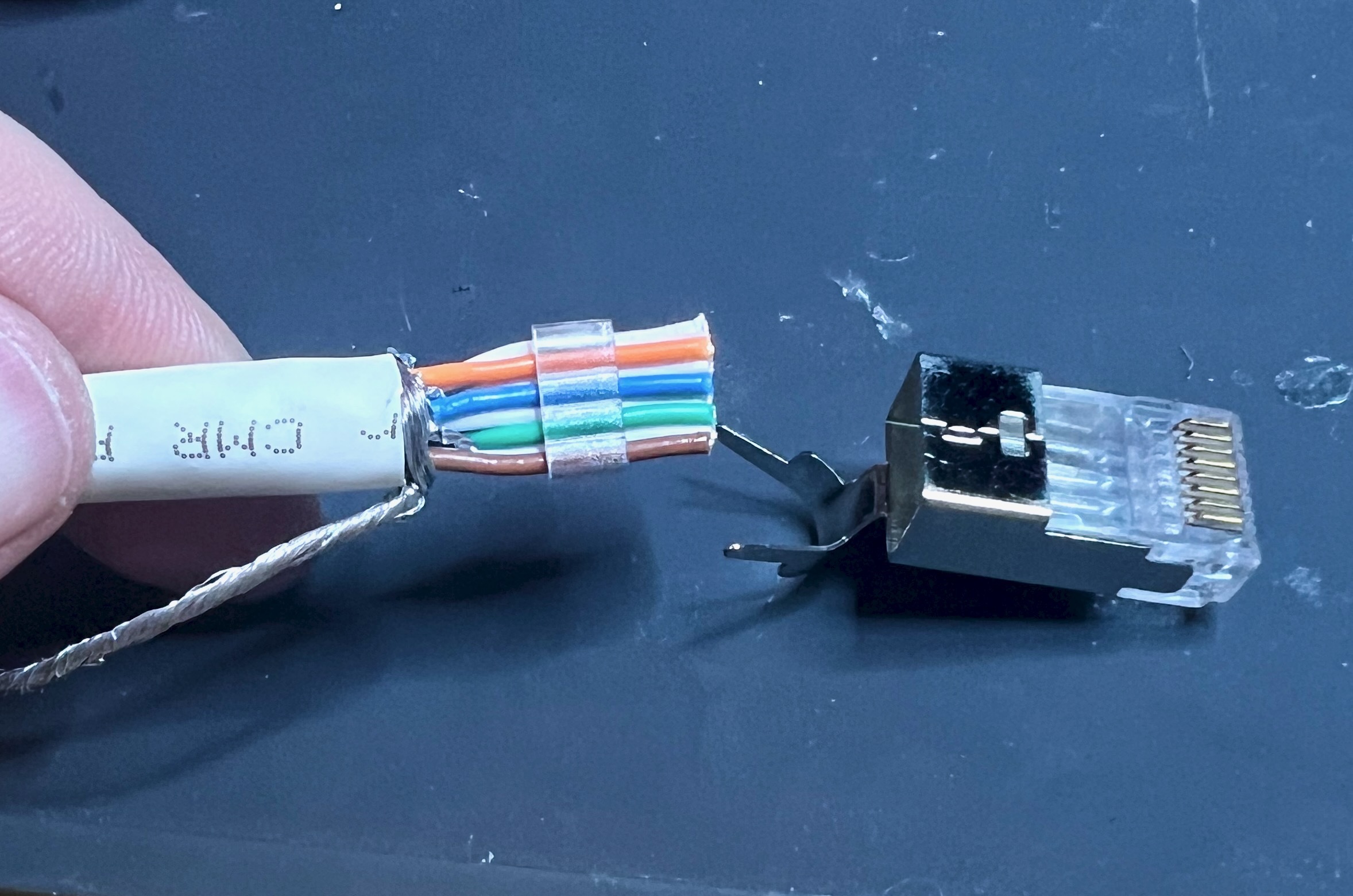
In addition to the length of raw cable we’ll need these parts for each end: connector body, internal wire guide, and a protective boot. These nest inside each other as the cable end is assembled
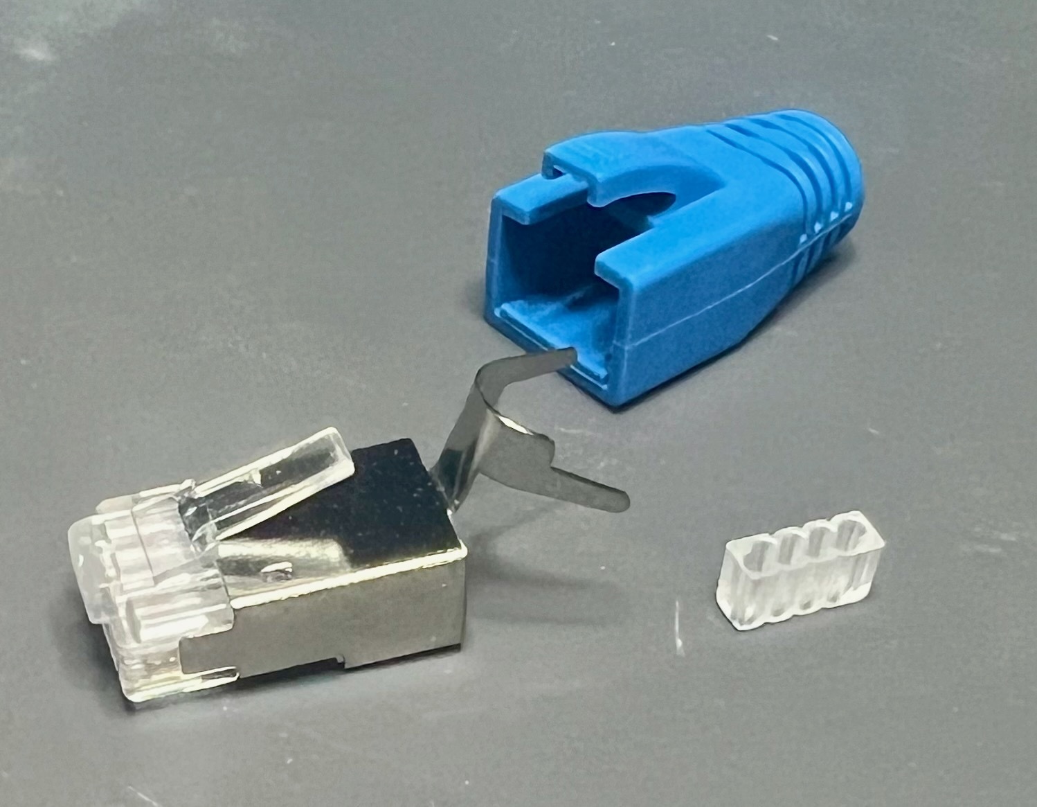
When your cable end has a boot, it’s important to put that part on the raw cable as step 0. If do not do this step first you will not able to do it later. Not all cables have boots but they’re usually present on shielded cables because the shield does not terminate inside the connector. Boots can also help keep cables safe while they are pulled and can help protect from tight cable bends too close to the connectors
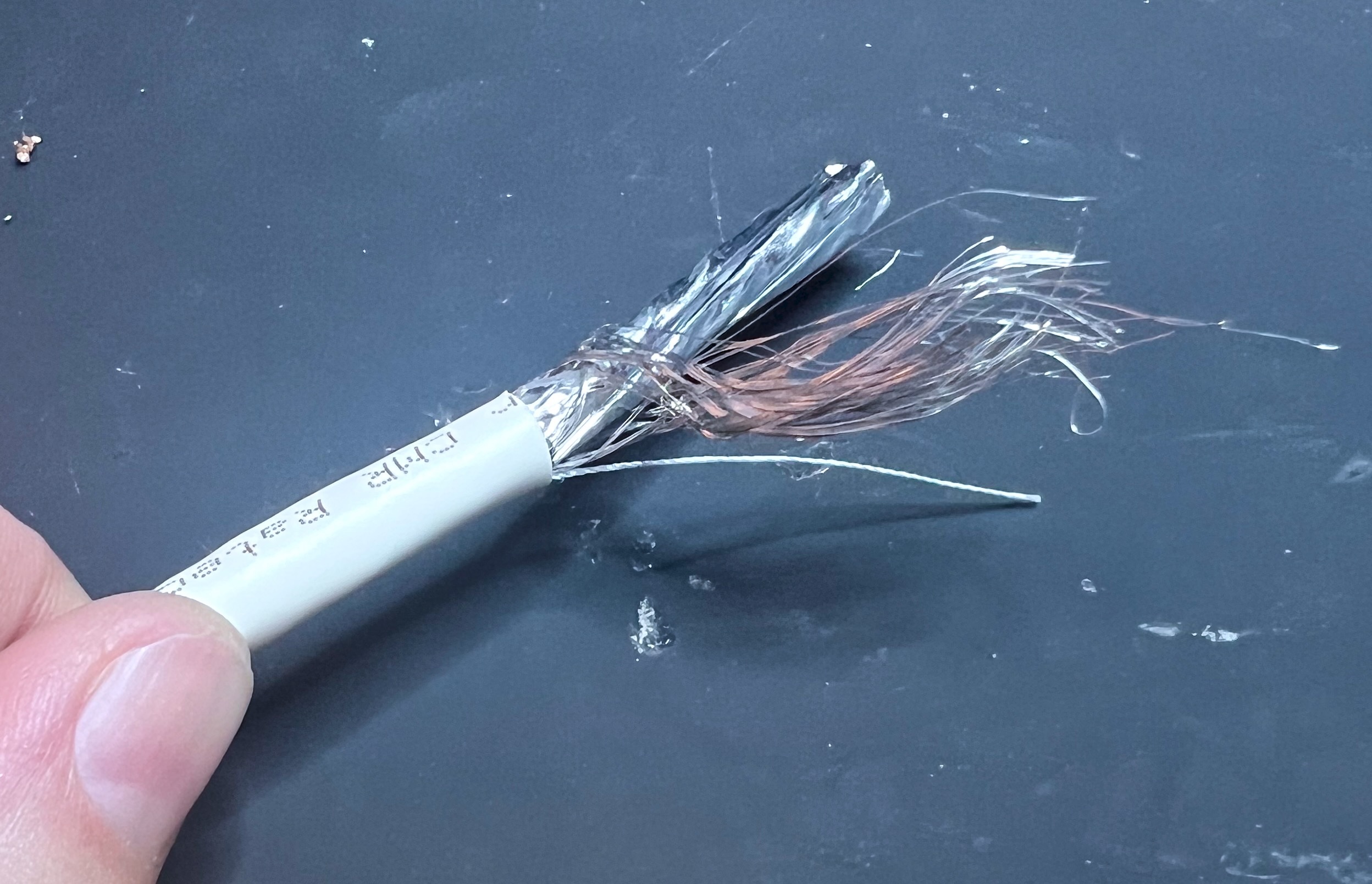
Step next is to remove about 1.5″ of the outer insulation. There are tools for stripping outer insulation from multi-wire cables like this, but it’s not very different than any other sort of wire stripping: make a cut around the circumference of the insulation and pull it off the end. Here you can see the outer shielding mesh, a thin thread to help keep the cable from stretching, and the individually foiled pairs that are then twisted together as a group
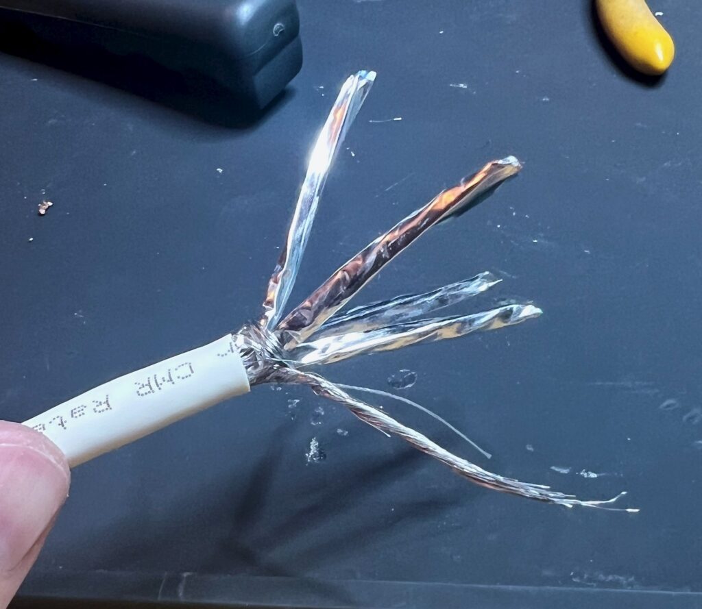
Next we need to strip back all the shielding and untwist all the individual wires. Excess foil is trimmed off and the shield mesh is twisted together. The twisted pairs are important for long-distance transmission but impossible to assemble into a connector and so must be unwound for the final segment. On shielded cables the connector is designed to provide shielding that connects to the cable and continues all the way to the transceiver
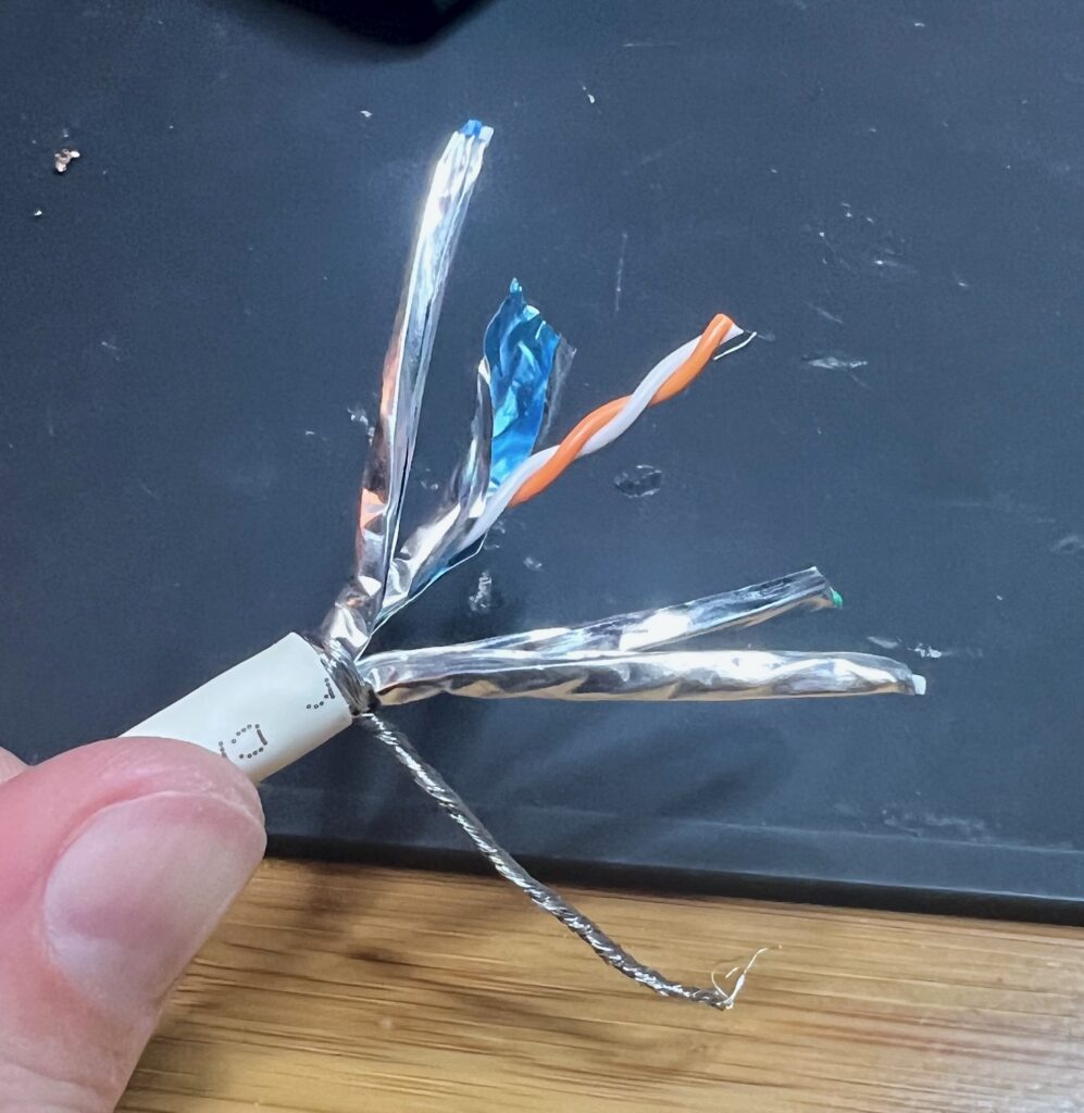
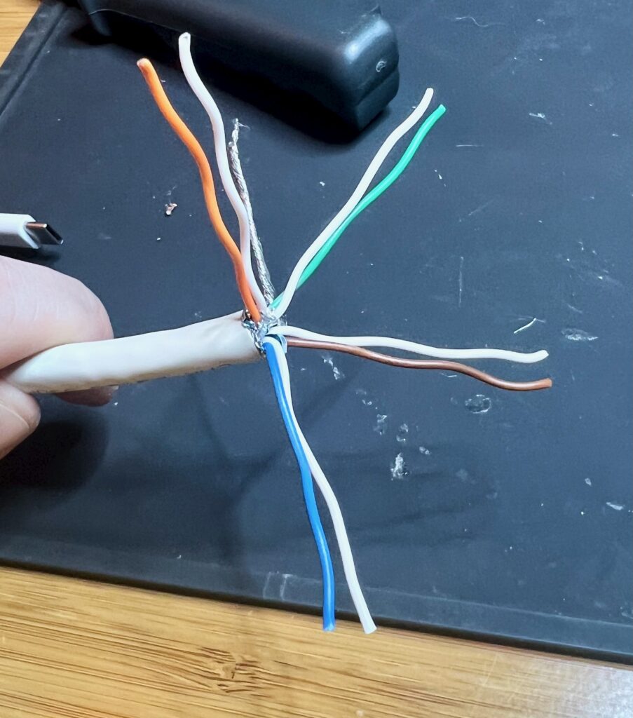
Note that the internal wires are color-coded: blue, green, orange brown, and that each one comes with a matching white cable. In cables without foil it’s common for the white wires to have strips that match their pair’s color, but in foiled cables it’s easy to tell which pairs go together and so the white wires don’t always get stripes
This color coding is important because the wires need to go into the connector in a specific order: ANSI/TIA-568. This order ensures that the two wires in each twisted pair are used for a matched set of signals, and that different Ethernet transceivers are compatible with all cables
The wires are first flattened, lined up, and trimmed, then inserted one at a time into the cable guide, then finally trimmed flush. The exact length needed for the flush trim varies a little from connector to connector, but in general you want it to be as short as practical while still being long enough to reach the end of the connector; the connector itself can provide a length guide
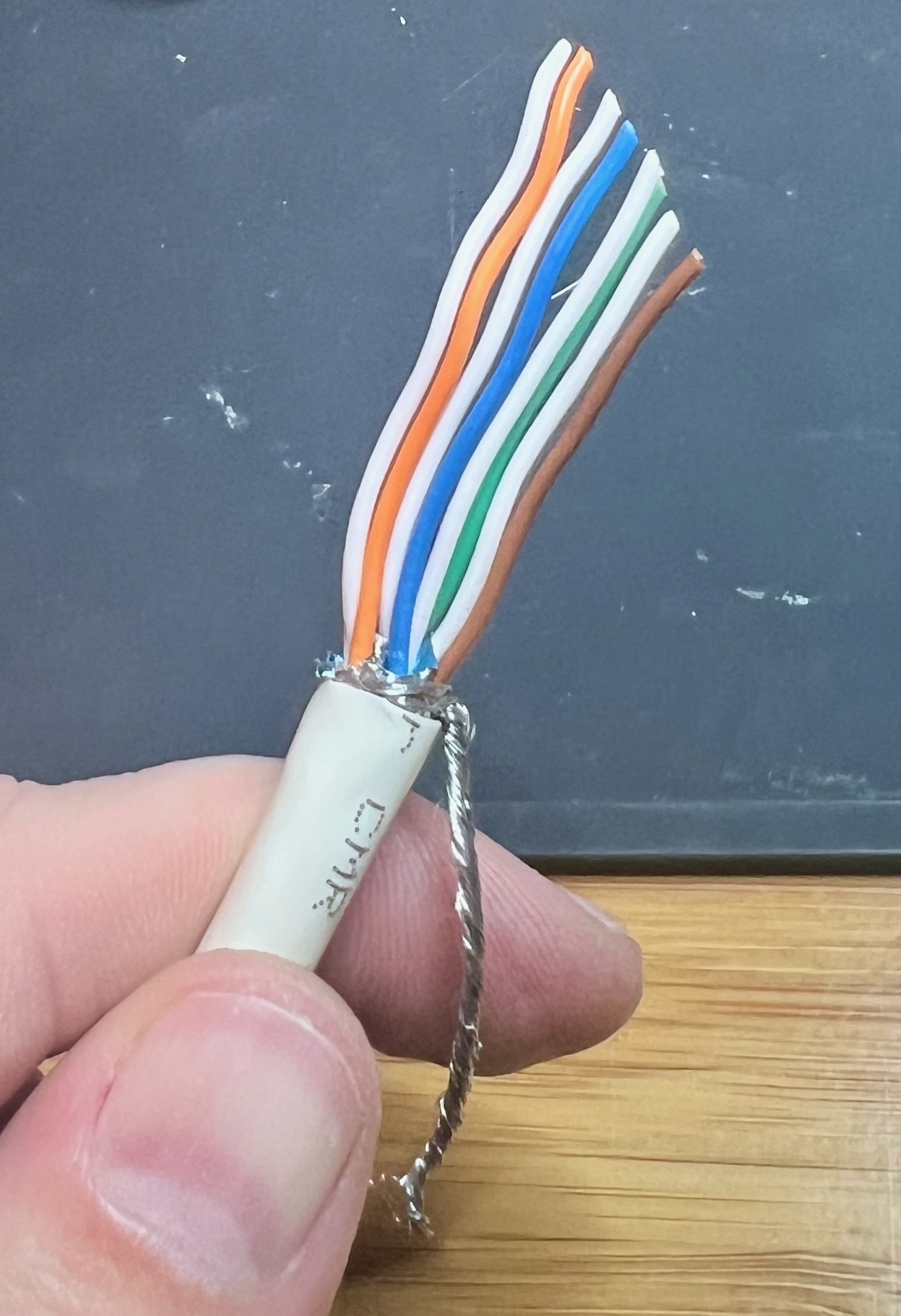
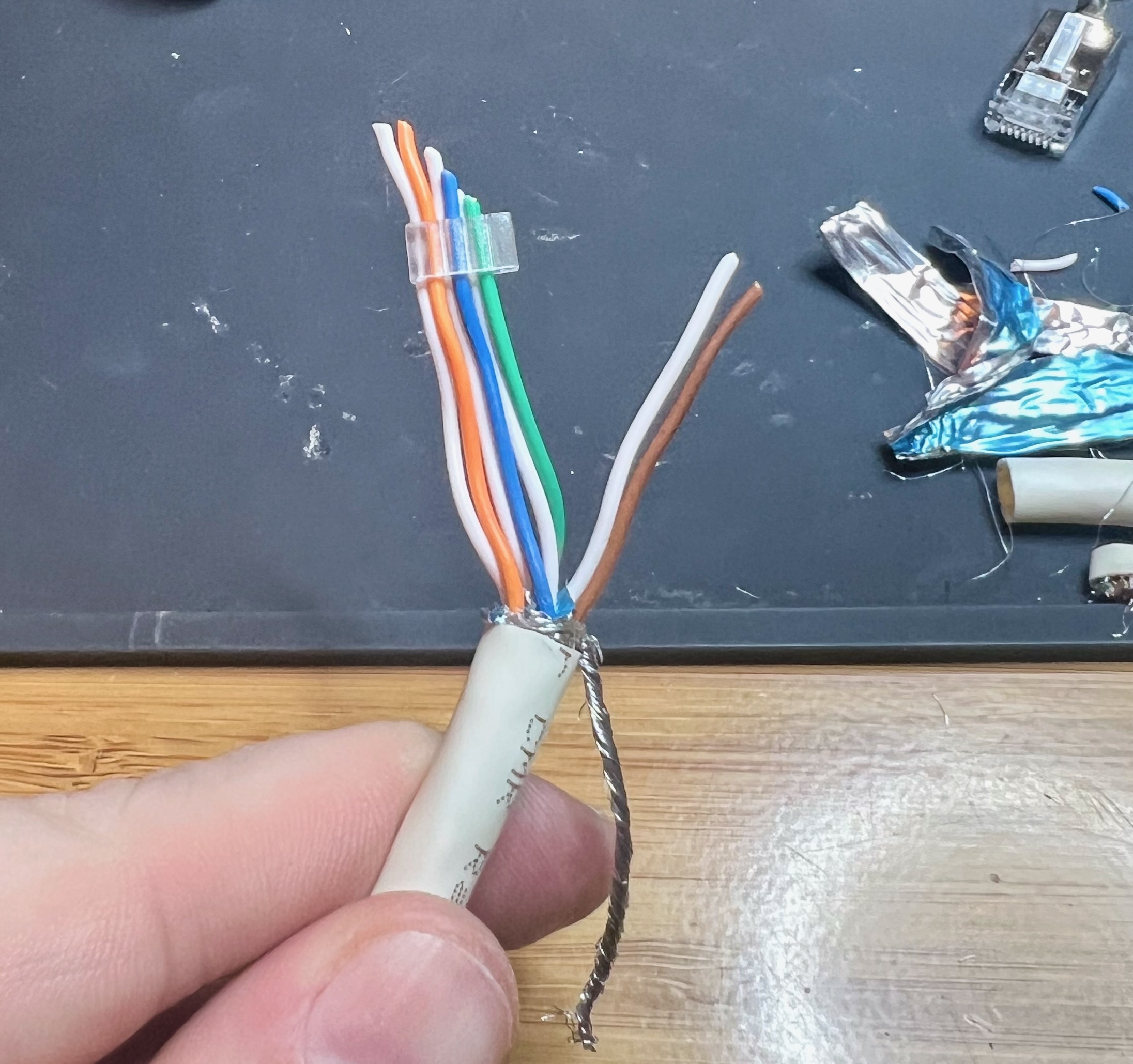
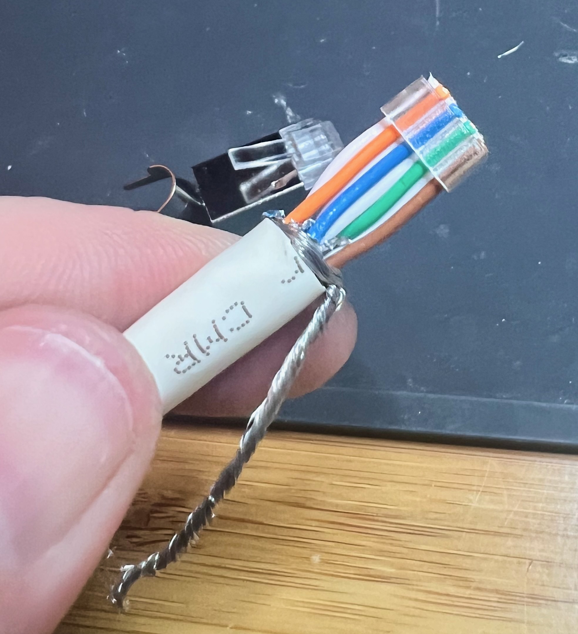
Once the wires all aligned in the guide the whole assembly is inserted into the connector. The wire guide helps keep everything lined up during the insertion until the wires slot into their individual pin slots. Because pitch of the connector pins is smaller than the diameter of the wires the wires are stagger-stacked on top of each other. Also note that the shield mesh is not inserted into the connector, as it does not connect to the pins
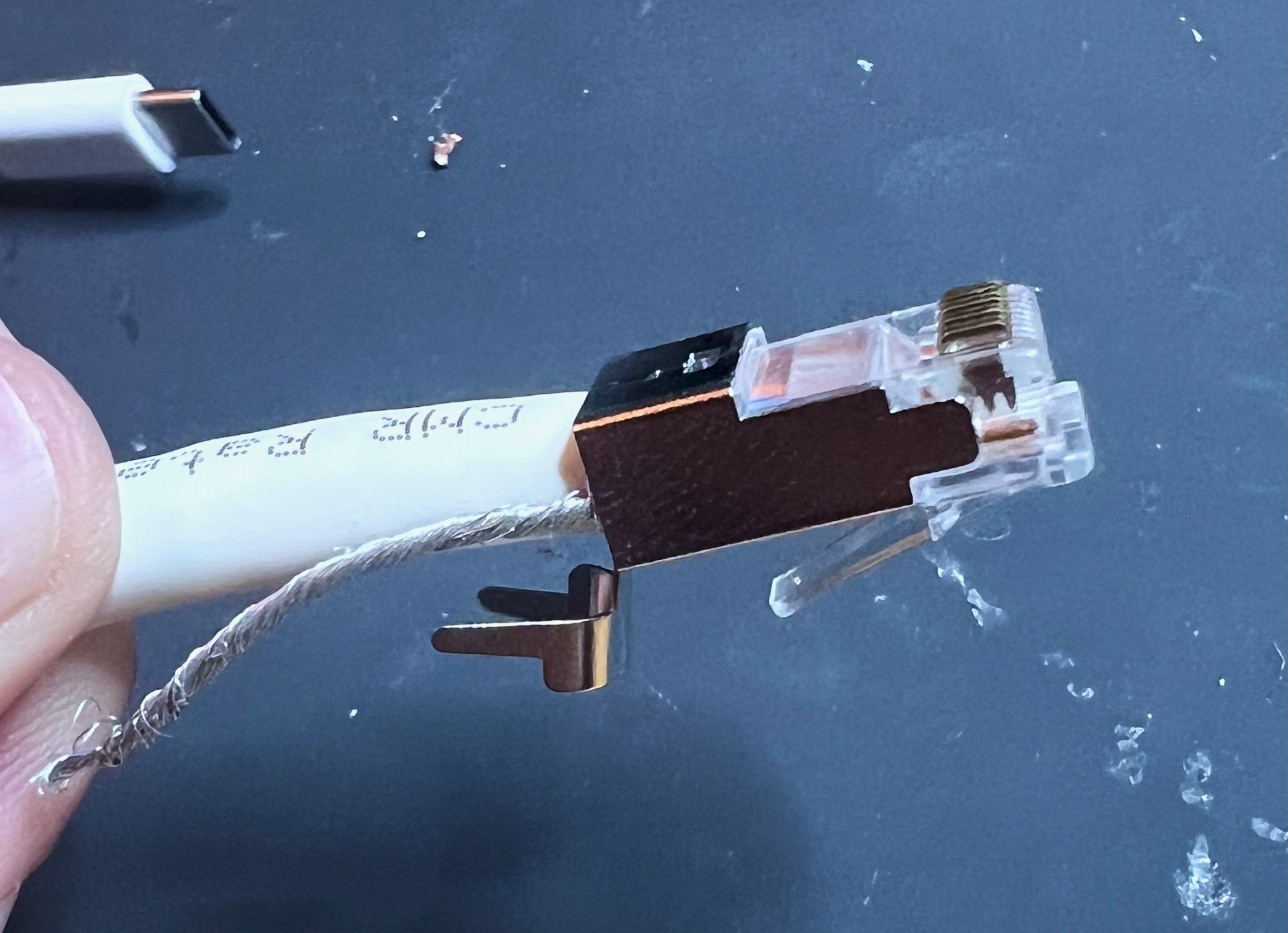
When inserting the wires it’s important to check that they all reach the front of the connector. If the wires were not all trimmed to the same length it’s possible for some of them to reach the end while others fall short. Connectors are usually transparent in part to allow visual inspection of the wire before the cable is finalized
In the side view you can also see the the pins are raised above the connector body, and that they have small teeth on the bottom side near each wire
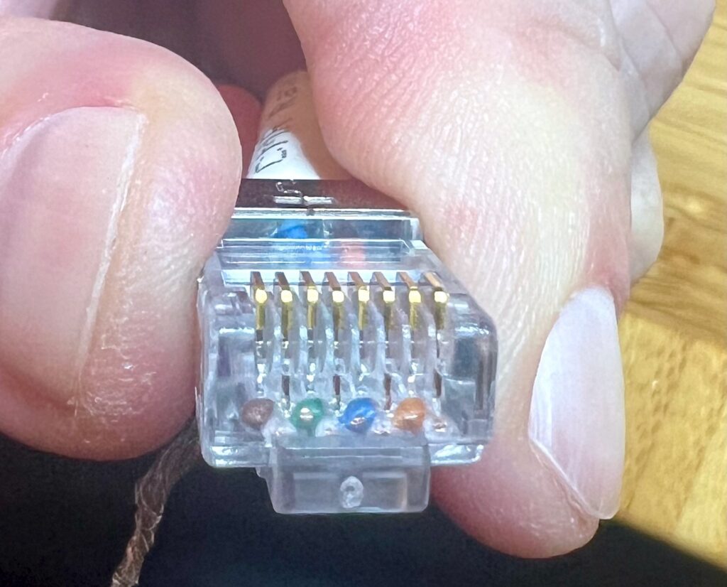
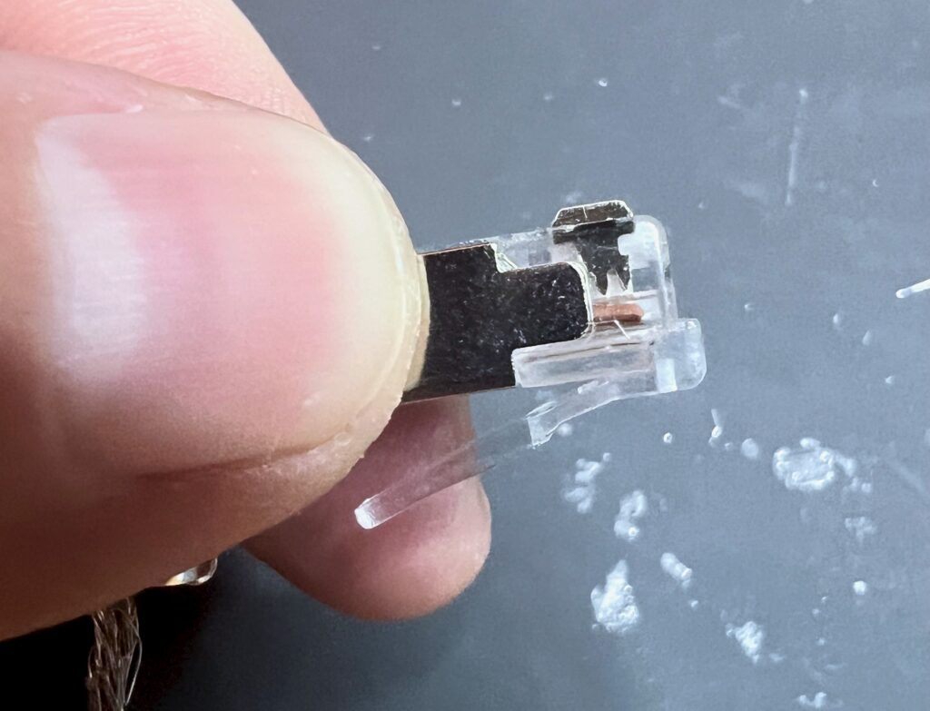
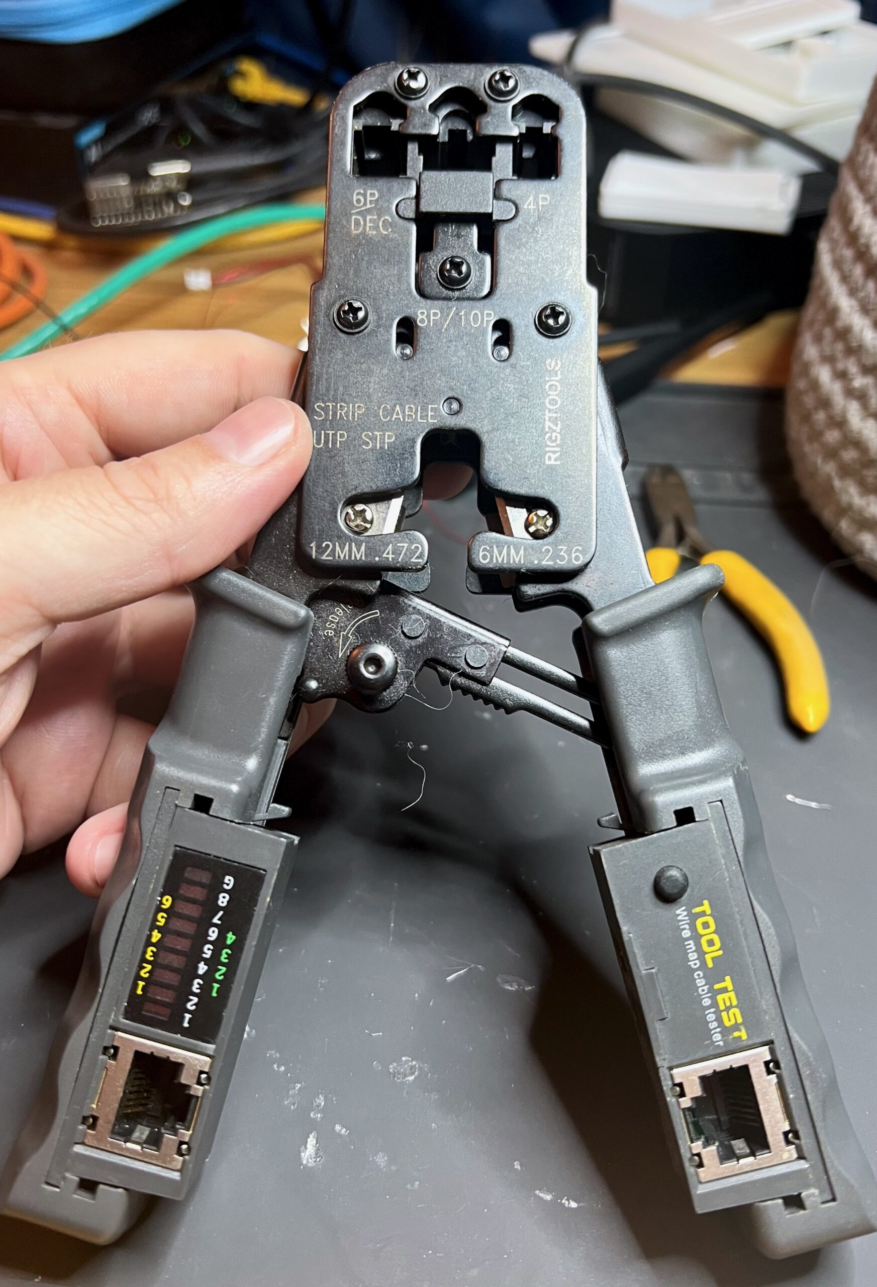
Once everything looks lined up it’s time to crimp. This step absolutely requires a special tool, which uses a pliers-like mechanism and a specially cut die that allows the 8 pins to be forced down into the connector body without crushing the body itself
This presses the teeth of each pin into its matching wire to connect it electrically and to physically lock it into place. There is also a section in the back of the connector body that is crimped less tightly to hold the overall cable in place; usually that rear crimp is intended to press into the part of the cable that is still insulated
After the crimp you can see that the pins have moved down and the teeth are now inside the wire. On this shielded cable you can also see that I wrapped the shield mesh around the connector shield tab, then used regular pliers crimp that tab around the entire cable. This provides both continuous electromagnetic protection and mechanical stability to the connector
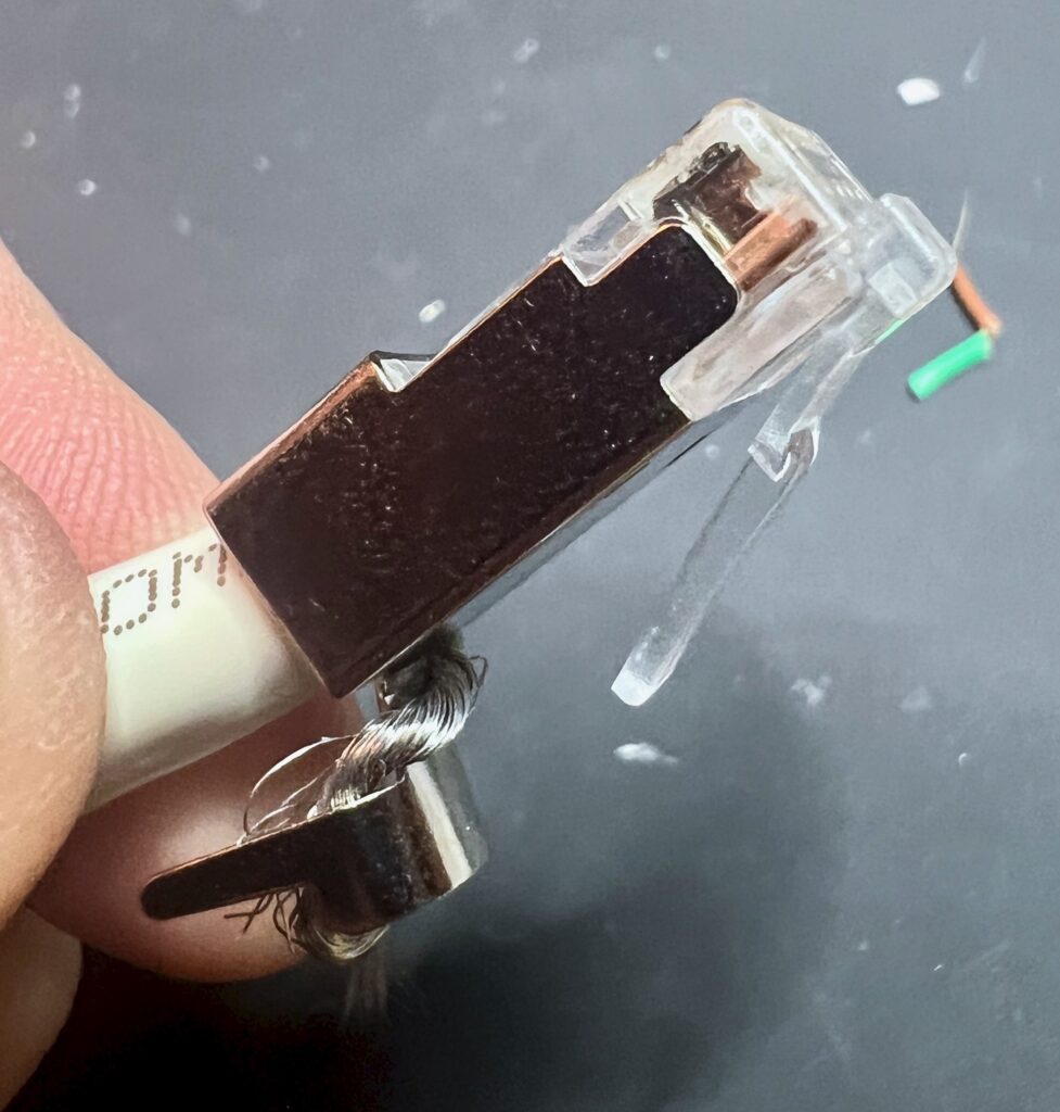
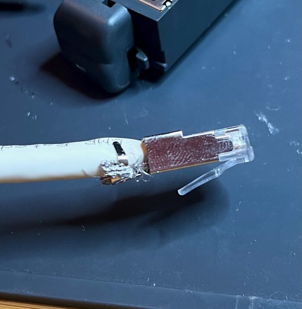
Finally the boot is slid over the back of the connector. Unless you forgot to do step 0 and then you will have to cut off the connector and start over
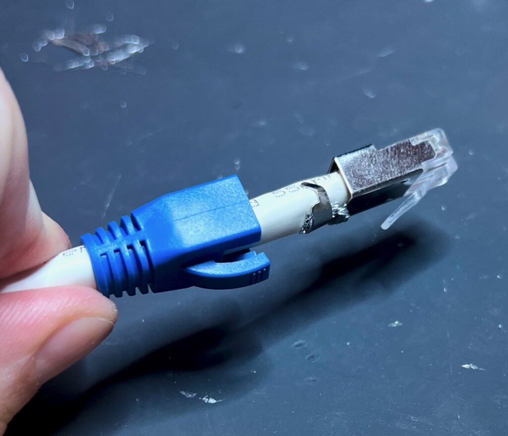
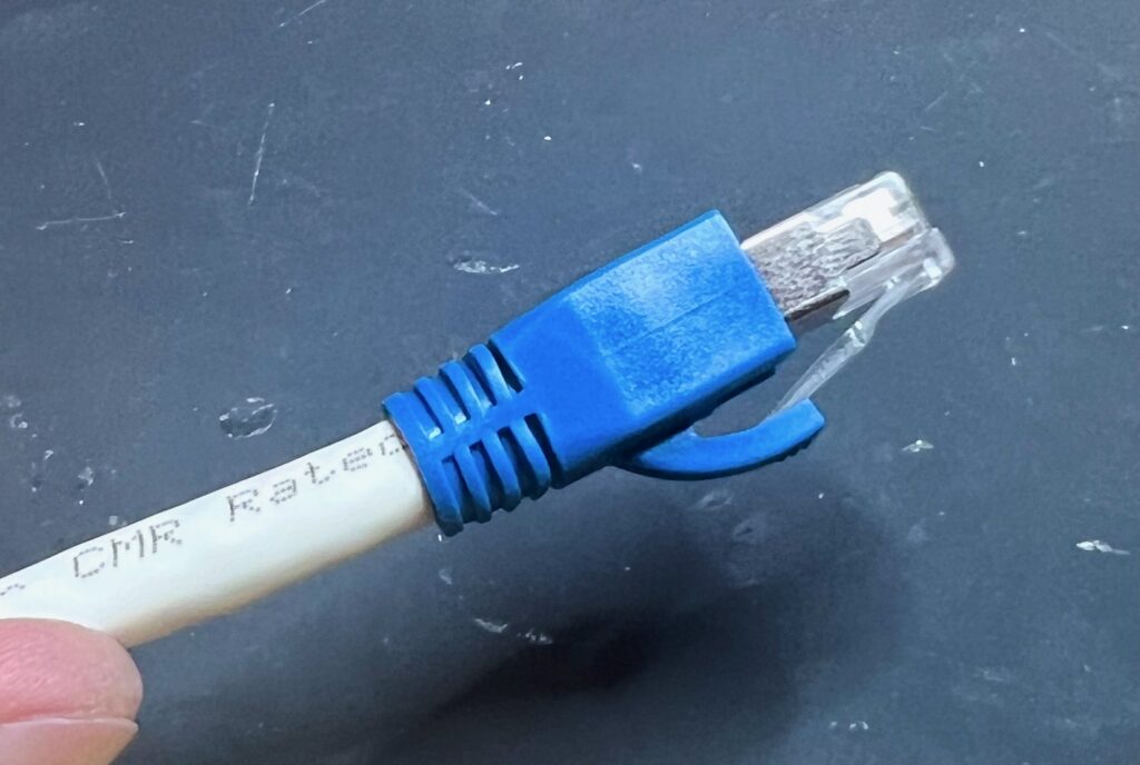
Then you’ll need to repeat the whole process for the other end. Both ends are wired identically. And if all went well you’ll have a functional Ethernet cable
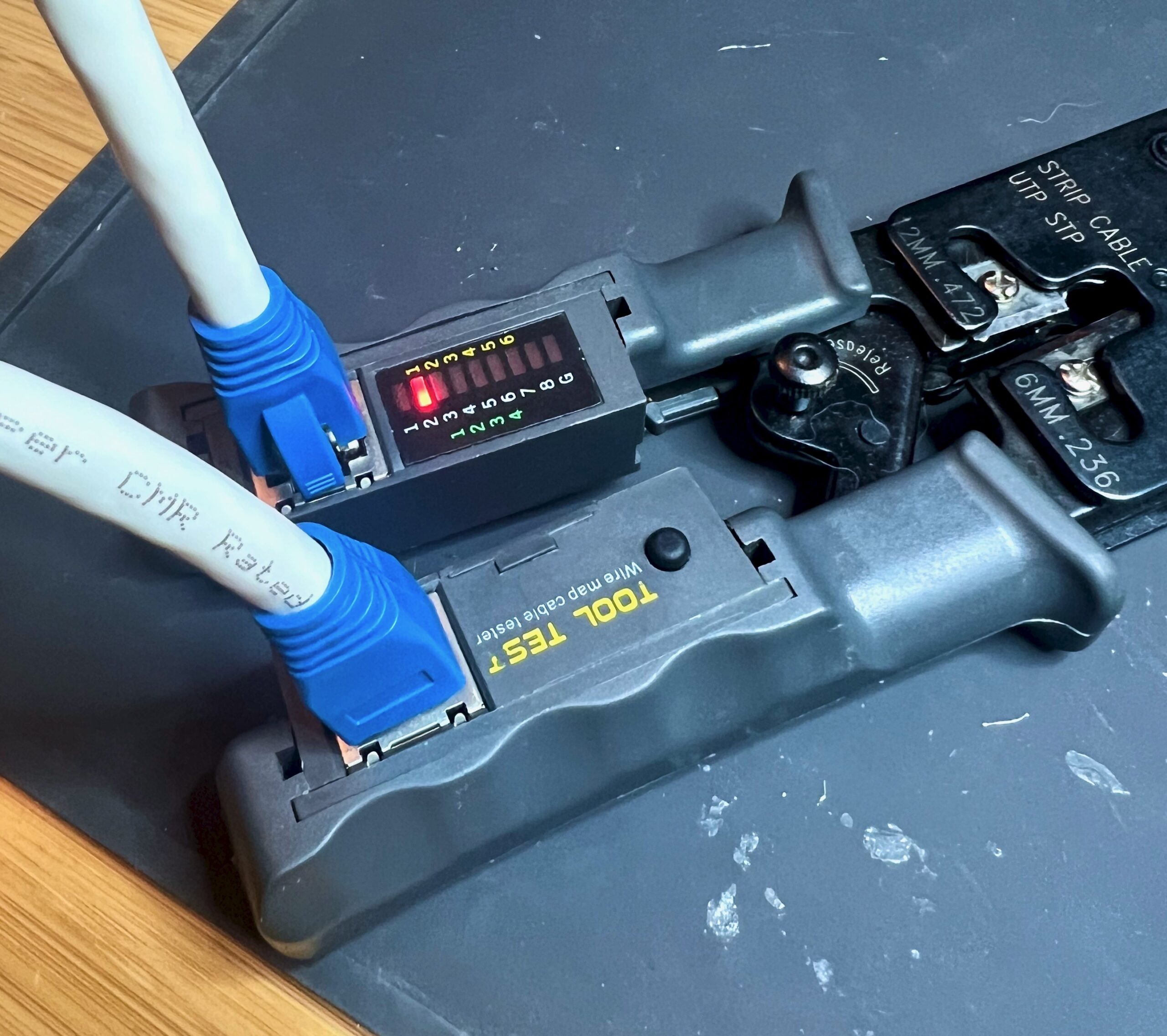
Since things don’t always go well it can be useful to test the cable. In theory you can do this just by plugging it into a pair of computers, but most computers can’t offer very much diagnostic information about cables, and can even hide problems when they use automatic retries
So it’s useful to have a cable tester. There are advanced testers that can evaluate many electrical properties of the cable, but a simple continuity check helps ensure that the wires are all connected. I have such a tester built into my crimping tool; it flashes a light using each of the 8 signal wires and the shield ground. If the lights all show in right order the cable is wired correctly
Cat 5e cables and connectors are somewhat simpler and usually do not have a wire guide because they don’t need as much precision, but otherwise follow exactly the same process as this Cat 6a guide
Unshielded cables will not light the ground light as the shield is used for that connection. Unshielded connectors will not have a shield tab and usually have plastic-only body where the only metal is the pins